Description of LC Gate Equipment and Local Train
Detection Equipment
A schematic of LC Gate Equipment along with Local Train Detection Equipment is given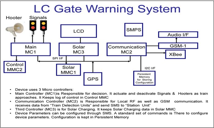 below:
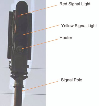
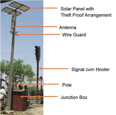
LC Gate Main Equipment consists of Micro Controllers; GPS, GSM & RF modules along with a suitable antenna, a MMC card for data logging and two 3-aspect signal units. Yellow and red are the two aspects in the signal units. These signals are as per IRS Specification issued by RDSO for two-aspect Colour Light Signal Unit. The hooter is fitted in its third bay, which is otherwise reserved for green light signal.
There are two solar panels providing power of 125W to LC Gate Equipment. The panels have must be capable of providing power for 96 hours. Besides the solar panels there are two 24V batteries of 150Ah capacity which supply power for 96 hours without being charged for four days. Battery Charger unit is used to charge batteries through solar panels. The Unit keeps a log of charging also. Suitable surge protection devices are provided at all the inputs.
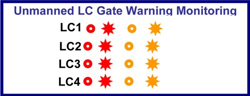
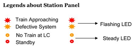
Two poles are used for mounting of signal, hooter and solar panel.  A concrete pole is provided with lightening protection. A schematic of LC Gate Status Indicator Unit at a railway station is given below:
It is a micro controller based device consisting of GSM and MMC units. It has a Micro Controller, a GSM Module, a LED panel and an SMPS as its main components.
Design Improvements
The initial design of the system was a micro controlled one but this was changed to a microprocessor based system since the former design was not scalable. The new system which is a Linux based one now works satisfactorily. The new design also does not use load cell device units due to its failure in some instances. The system is able to detect only trains equipped with Simran units. Further, to avoid failure of the system the trains are fitted with an auxiliary Simran unit, in addition to the main unit.  The auxiliary Simran uses a separate power source, as also separate GPS and RF modules. Under normal working conditions, both units broadcast required data. When main Simran unit fails, the auxiliary unit continues to broadcast the data. Whereas the earlier design used a single hooter fixed on the pole on which antenna and solar panels are fixed, the improved design uses hooters on the signal poles in the slot which normally holds the third light, green. The new design has been tested with four trains at a time, though it has the capacity to support up to 32 simultaneous trains. The unit has also been tested successfully with train shunting.
ULCGWS has been tested out on a pilot basis on the Kanpur – Lucknow track. It will be implemented once the Railways finish the deployment of the Simran project.
The domain knowledge for the project was provided by Research Designs & Standards Organisation (RDSO), Indian Railways, Lucknow & Signal & Telecom Directorate while the project was developed completely at IIT Kanpur.
B M Shukla
Principal Software Engineer
Computer Science Department
Indian Institute of Technology – Kanpur
Prof S G Dhande
ME/ Computer Science Department
Indian Institute of Technology – Kanpur
 TrafficInfraTech Magazine Linking People Places & Progress
